Drawing Tools
Sheet Setting
It is now possible to add design notes to the frame and the frame selection, for example A4, which can assist in aligning and improve the look of printed schematics and PCB designs.
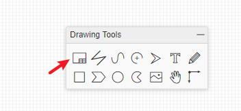
Click the frame/drawing/document button like in the image below:
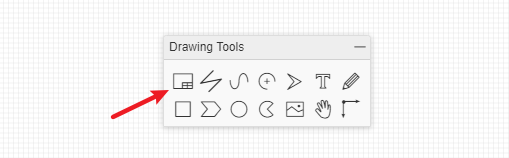
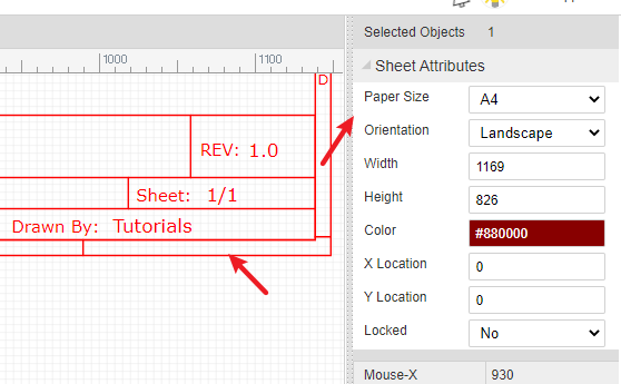
And you can edit the blue text when you've selected the text attributes or double clicked it.
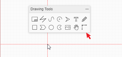
The bottom right zone can be selected and dragged or the frame can be dragged and deleted.
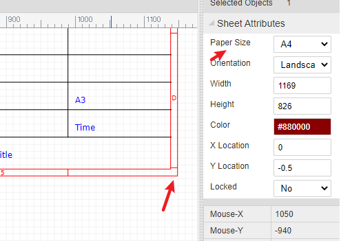
When you've selected the bottom right zone, you can edit the sheet attributes:
Custom Sheet
EasyEDA supports the schematic diagram drawing frame required by custom. At present, custom drawings need to be placed manually, and automatic reference of custom drawings is not supported when creating new schematic diagram.
How to create:
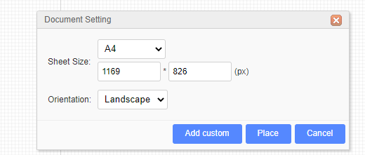
Click the "Sheet Setting" button at "Drawing Tool".
Click "Add Custom" button.
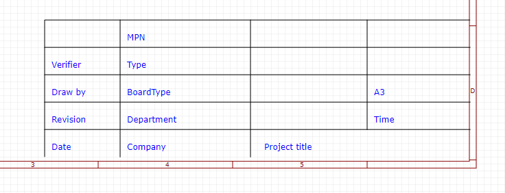
It will create a new symbol editor, you can edit the table by line as you want, as below:
Select the outline, you can edit its size.
Save it. You can place it in schematic such as a part at "Library".
Line
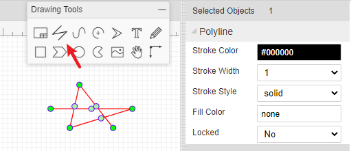
In the Schematic editor, you can draw a line with any direction. You can change its attribute as in the image below:
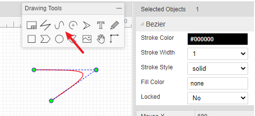
Bezier
With this tool, you can draw a pretty cool pattern.
Arc
You can draw the arc of any shape.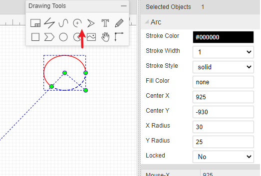
Arrow Head
You can add arrow head to marking text or important part.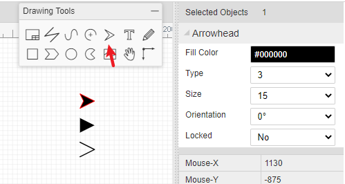
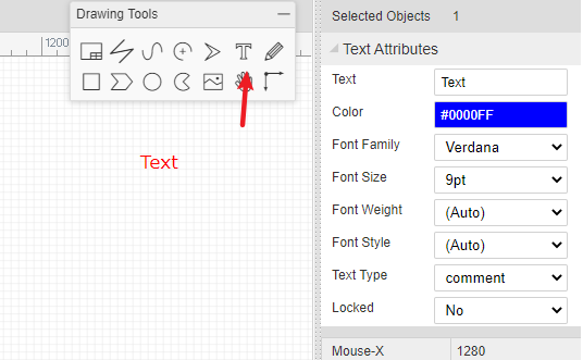
Text
Text attributes provide many parameters for setting:
- Text: You can change text in inner box or double click the text. For every new text, the default text is
Text. -Color: Defines text color. -Font-family: It provides 12 fonts for choosing. -Font-Size: Defines Text size. -Font-weight: Defines Text weight. -Font-Style: It contains (auto), normal, italic. -Text type: types include comment and spice.
The editor will remember your last text parameters.
Image
When you select Image from the Drawing Tools palette, an image place holder will be inserted into the canvas:
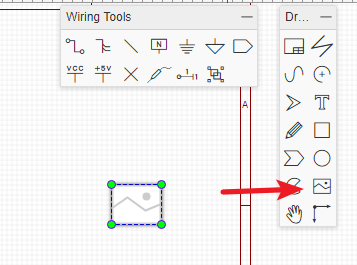
Select the place holder, so you can see the image's attributes in the right hand Properties panel: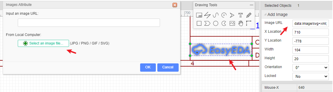
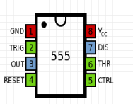
Set the URL of your image. For example, setting the URL to:
http://upload.wikimedia.org/wikipedia/commons/thumb/c/c7/555_Pinout.svg/220px-555_Pinout.svg.png
will make your image look like this:
Please note: at present, EasyEDA cannot host images, so you need to upload your images to an image sharing site.
Drag
If you want to move some kind of parts and wires, you can use drag, hotkey D.
Or you can select the parts and wires area firstly and move them. 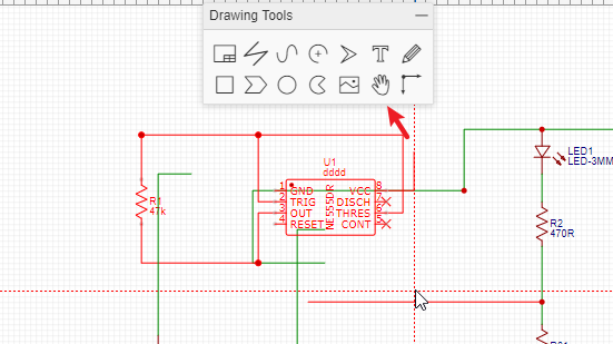
Canvas Origin
Canvas origin default is set at left top corner of the schematic sheet, but you can set it where you want via Canvas Origin.
For another way to set canvas origin, you can try Top Menu> Place > Canvas Origin.